The entire submarine is covered with a Glass Reinforced Plastic (GRP) fairing. The passenger viewports are manufactured from see-through acrylic. The fairing is assembled on a steel frame bolted to the hull attachments. The plastic fairing acts as an outer hull protecting the viewports, thrusters, piping, etc., and giving hydrodynamic form.
The upper deck is surrounded by a railing. The large mast frame offers attachments for cameras, lights, and other devices.
The passenger compartment is lined with aircraft-style facia panels. Above the viewports, the panel forms a console gathering emergency breathing system, internal communication system speakers, life jackets, and emergency rations.
PRESSURE HULL
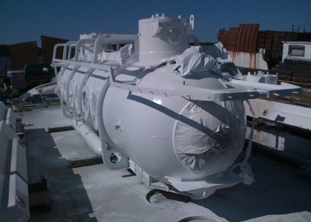
The pressure hull is a cylindrical structure with hemispherical ends and two entrance towers. The pressure hull is divided into three compartments:
- Pilot compartment
- Passenger compartment
- Engine room
The pilot compartment is fitted with one 1000 mm hemispherical viewport for pilot use. The passenger compartment is fitted with 12 viewports, 600 mm each. Entranceways are located in the opposite ends of the passenger compartment. The aft entrance is the main, primary means of access/egress & the forward entrance is the emergency access/egress.
The hull is constructed from DnV classified steel grade NVE or equivalent. All hull welds are 100% NDT tested. The customer will receive material inspection reports and certificates.
PROPULSION SYSTEM
The submarine has a fully hydraulic propulsion system. The main forward/aft control is done with two main thruster units situated at the aft end of the vessel. The lateral thruster unit is placed at a bow above the pilot’s viewport. The vertical control is achieved with one thruster fitted in the bow. The hydraulic system is fully pressure compensated thus following the changes of the external pressure. The tank is mounted outside the pressure hull. The hydraulic power pack and valve block are located in the engine room. The power unit is mounted on vibration dampers and connected with flexible hoses to the system. This will ensure that the noise level is acceptable in the passenger compartment.
ELECTRICAL SYSTEM
The electrical system of the submarine is battery powered from 248V and 24V battery packs. The primary consumers like propulsion, lightning, etc. are powered by 248VDC power. The auxiliary devices like communications, life support, etc. derive their power from 24V batteries. The 248V supply is distributed from a remote-controlled distribution panel in the engine room to the consumers that mostly also are situated in the engine room. The 24V distribution panel is fitted in the pilot compartment. All circuits are selectively fused to protect the all-around function of the submarine.
All batteries are located under the passenger compartment floor. The lead-acid air circulation cell batteries are mounted in acid-proof boxes that are supported to the compartment walls with spacers. This enables free air circulation inside the compartment.
BALLAST AND BILGE SYSTEMS
The soft ballast (air ballast) system is used to give the submarine sufficient freeboard and stability on the surface. The soft ballast system includes external tanks, tank valves, and internal control valves. The tank valves are air-operated normally closed piston valves. At the beginning of the dive, the valves are activated and the air escapes from the tanks causing the submarine to descend. After the valves are closed the tanks can be blown again with pressure air.
The buoyancy of the submarine is controlled with the hard ballast (water ballast) system. The hard ballast system includes internal water tanks, pumps, and valve manifold. The capacity of the system is designed to compensate for the changes in the number of passengers on each dive. If correctly operated then, the immersed submarine will be neutral or just slightly buoyant.
The fixed ballast consists of steel and lead blocks bolted to the submarine’s keel. The exact amount of fixed ballast is determined after the buoyancy tests. Each of the bilges has a separate suction line to the bilge pump located in the pilot compartment.
GAS SYSTEMS
The pressurized air system is divided into main and reserve air systems. The air is stored in two 200bar/250l cylinders. The high-pressure air is brought into the pressure hull via two independent penetrators with internal and external hull stop valves. The air is divided to the consumers in the gas panel located on the left side of the pilot.
The oxygen is also divided into main and emergency systems. The oxygen is stored in six 200bar/50l cylinders. The oxygen is brought into the pressure hull via two independent penetrators with internal and external hull stop valves. The oxygen distribution and flow adjustments are controlled from the gas panel.
NAVIGATION SYSTEMS
Two video cameras are mounted on the top of the mast frame giving the pilot a surface view on a video monitor in the pilot compartment. In front of the pilot, there is mounted the steering control panel incorporating a control joystick, thumbwheels, and thruster function indicators. The other units in the steering console are an echo sounder, (optional extra) magnetic compass, and electronic compass display. Additional units used in navigation are trim and heel indicator and mechanical depth gauge.
TWO NAVIGATION LIGHTS ARE MOUNTED IN THE MAST FRAME AND RAILING
The external lights are halogen or LED type giving a high light effect with low power consumption. The lights are mounted on each side below the passenger viewports. The pilot has two forward facing lights.
A surface marker buoy can be used if required to mark the location of the submarine when dived.